to the level of information in the Haynes workshop manual , buy one here on Amazon UK .
if you know nothing about electrics like i did not when i first started out , read this book from Amazon UK
this will save you £100s in repair bills and has easy to follow instructions , and some excellent
tips and advice , literally makes electrical fault diagnosis simple .
Yamaha YBR 125 wiring and electrical post .
battery - 12v 6ah
bulbs
headlight bulb - 35/35w
sidelight bulb - 5w
brake light bulb - 21/5w
plate light bulb - 5w
indicator bulb - 10w
clocks bulbs - 1.7w
15a fuse
Yamaha YBR 125 charging system resistance figures
stator coil - 0.6~0.95(05~06) 2007-on (0.45~0.67)
regulated volts - 13.7~14.7
0.1ma max volt leakage
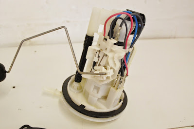
Yamaha YBR 125 fuel level sender unit resistance figures
full - 4~10 ohms
empty - 90~100 ohms
injection system resistance figures
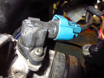
crank position sensor - 248 ~ 372 ohms @ 20 degrees C
engine temp sensor - @ 20 degree C~2.5-2.8 ohms - @ 100 degrees C~210-221 ohms
fast idle solenoid - 31.5~38.5 : 25 degrees C
intake air pressure sensor output voltage - 3.75~4.25V
intake air temp sensor resistance - 2007-2009 2.4 to 2.9 k-ohms 2010 on 5.7 to 6.3 k-ohms
throttle position sensor input voltage 5v output throttle closed 0.63-0.73v
tip over sensor voltage output - upright 0.4-1.4 ~ 65degree angle 3.7-4.4v
other electrical posts
Yamaha YBR 125 Generator , Alternator Stator testing
Yamaha YBR 125 Not sparking no spark diagnostics
 |
| yamaha ybr 125 wiring diagram |
 |
| yamaha ybr 125 2007 wiring diagram |
and see below key to above diagram larger here
some photos off my latest Yamaha YBR 125 - ill update soon with id of parts and wires .
regulator
cdi unit 3d900
On the left hand side under battery cover you have the solonoid ( brass ) with fuse , if you have a failure to turn bike over it could be this , flasher unit ( black ) , and headlamp relay ( white )
=================================================
Test battery at the negative and positive terminals
If you have a voltage meter you can do some basic tests.
When the engine has been off for at least 1-2 hours with ignition key turned off,100% Charged 12.60 to 12.8v
75% Charged 12.4v
50% Charged 12.1v
25% Charged 11.9v
0% Charged less than 11.8v
========================================================================
Heres some excellent motorcycle electrical test videos .
Must have electrical tool
12v circuit tester mines snap on but hard to find in UK click here for any on Ebay UK now.
Kewtech multimeter , there are better and worse .this has always done everything ive asked of it and would recommend them , you can get a lot cheaper . see here on Ebay UK
Power Probe , dont use that often but an excellent tool when needed mine is a cheaper version this one here in ebay UK
you can get Snap On Powerprobe which is excellent if you can afford it it see them here on ebay UK
My S.W.A ratchet electrical connector crimps , i paid a lot of money for these when i worked as an electrician but still paying for themselves
now 10 yrs later
cant find this model but heres some on ebay UK a lot cheaper these days
thats about it for interesting electrical tools i own , got any recommendations send a comment below .


Thank you for providing this information. Please tell me where the red and white trigger wires go on the six pin CDI.
ReplyDeletenice
ReplyDelete